Joystick Hack
December 7th, 2011
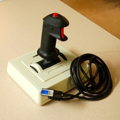
It's hard to describe how satisfying it was to reverse engineering a joystick that I grew up playing Microsoft Flight Simulator on long before I knew anything about circuits. My family bought and used a CH products FlightStick in the mid 90s and then it probably sat in a closet throughout the following decade, just waiting to be used again. On my trip home this fall I brought it back with me so I could have a go at making some kind of use out of it.
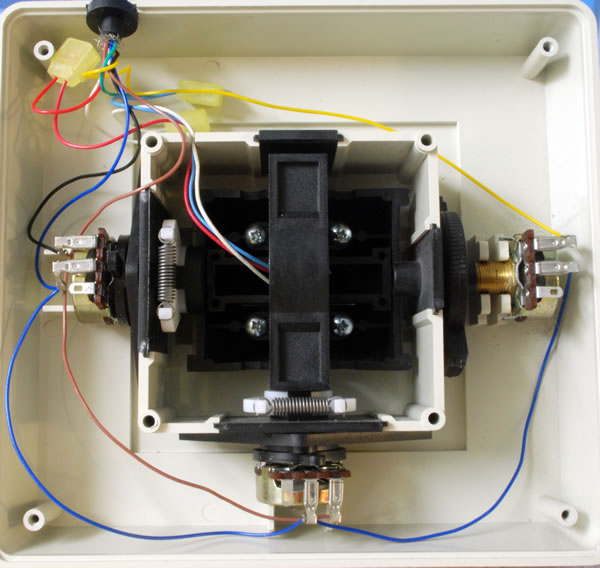
I was excited when I opened it because I saw that the whole circuitry uses only three potentiometers and two momentary switches — perfect for hacking and hooking up to an Arduino! Two of the potentiometers are used for the x and y axis, while the third is used as a slider. The two switches are used in the two buttons of the controller.
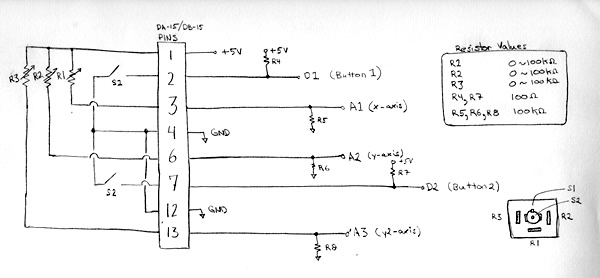
To get started I diagrammed out the internal circuitry. Then I needed to figure out which internal wires went to which of the 8 pins on the DA-15 connector. I actually did this the hard way using my multimeter and trial and error before I learned that GamePort controllers' pinouts are well documented. I also found some other good documentation at ePanorama.net.
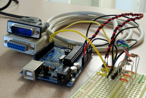
I didn't want to cut the cord coming out of the controller so I ordered an extension cable for about $8 on Amazon.com. I cut this in half and used my multimeter to match the wire color to the pin number. You can do this by measuring the resistance from each colored wire to each pin. When you you've found a zero resistance (short circuit) you've matched the wire color to the pin!
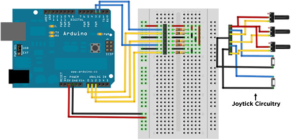
At that point the joystick circuitry was known. It was time to hook the joystick up to the Arduino to convert the analog voltages to a digital reading and then send that out the Arduino as a string through the serial port. To do this I set up a voltage divider for each potentiometer and a 100 Ohm series resistor (to avoid a short circuit) for the momentary switches. I measured the max values of the potentiometers to be about 100 K-Ohm so I paired those 100 K-Ohm resistors to yield an output voltage of 2.5 to 5 Volts.
The Arduino code takes these analog signals, converts them to digital values and then sends them out the serial port in the format "<R1 R2 R3 S1 S2>", where R1, R2, and R3 are integers between 0-1023 and S1 and S2 are either 1 or 0, where 0 represents a pressed button.
The final piece to this project was to write a Processing sketch that reads the data through the serial port and renders a graphical representation of the data. Luckily, I already had some code to reuse for reading the serial port, as well as for rendering a simple 3D cylinder to represent the joystick. The Processing code also includes a calibration routine in case the values drift.
You can view my Arduino and Processing code in my github repository for the project.
Media:
Images